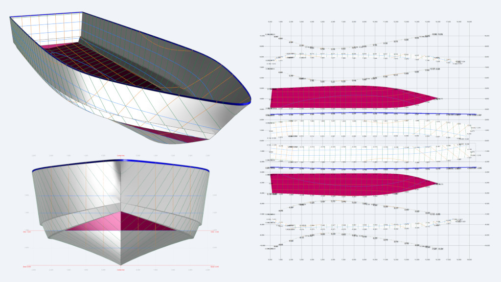
Introduction to SWATHs – Part 2

In Part I, we discussed the basics of what a Swath is, where it comes from, how it differentiates itself from other vessels, and how to define it hydrodynamically. In this part, we shall discuss the implications of a vessel in a sea state, how this relates to motions and hence accelerations, and why a Swath is far superior to other vessels in a rough sea.
Seas and Motions
For this, we first need to understand how the sea and a vessel interact, particularly in relation to the vessel’s natural motion periods. These natural periods can be directly linked to key wave characteristics—such as wave height, wave period, and, importantly, the speed at which the vessel encounters the waves. This relationship can be described mathematically by the following equation [1]:

From equation [1], we can calculate the period or frequency of encounter (ωₑ) by using fundamental wave characteristics, such as wave period, wavelength, and wave speed, along with the vessel’s speed (Vₛ) and its heading relative to the incoming wave train. This heading is expressed as the cosine of the encounter angle (cos φ), where 0° corresponds to head seas and 180° to following (stern) seas.
If we now consider any small vessel, whether monohull or catamaran, between 10 and around 40 metres, these vessels all exhibit similar natural periods of roll, pitch, and heave in the order of 2.5 to 4 seconds. If we now plot the period of encounter versus the vessel speed, using the above formula, based upon a typical sea spectrum of the North Sea of Hs = 2.0 m wave with a typical period of 6.5 s, in head seas (0°), we get the following curve:

The red shaded box shows the typical natural periods for vessels between 10 and 40m. What can be seen is that from about 12 knots onwards, conventional vessels will exhibit uncomfortable behaviour, because the natural period of the vessel coincides with the period of encounter with the waves, an effect known as resonance.
Resonance is where the two periods (in our case, the wave encounter period and the vessel’s natural period of motion) match each other. When this occurs, the vessel movements are characterised by being very unpleasant and sometimes violent, just like a car driving over a series of speed bumps perfectly spaced to the wheelbase of the car. The effects of resonance can be significant and produce extremely uncomfortable motions resulting in seasickness and general fatigue, and if unchecked, can become life-threatening. The only means to minimise these motions is simply to slow down, which is what all vessels do when the seas become rough, or, where possible, use a vessel with its natural periods of motions that do not coincide with that region of the red box whilst traveling at speed.
If we now consider that same 30 m high-speed catamaran shown in Part I, which has a roll period of 2.7 seconds, we can plot this on the same graph. If we also plot a 26 m Swath with a very similar length and displacement, with both vessels traveling at 25 knots, the natural roll period of the Swath is 9.1 seconds. It is very clearly evident that a roll period of 9.1 seconds is significantly far away from the shaded red-box region of typical natural periods for these 10-40m vessels, shown below.

What about changing the heading? Let’s investigate this further. So below is the same graph of ‘encounter versus vessel speed’, but with vessel headings relative to the sea state, from head sea to bow quartering seas (45°) and to beam seas (90°).

We can see that changing course, from a head sea to a bow quartering sea, that is a wave train at roughly 45° to the vessel’s course, has some effect, but not overly so. It does increase the range from 12 to 16 knots before resonance begins to occur.
So, what about beam seas? Is this away from the red zone of resonance? We can see that in this sea state, the encounter period is the same as the wave period, this being 6.5 seconds, because, assuming a parallel wave train, the vessel’s heading is at 90 degrees to this moving wave train. So, assuming changing course by such a significant amount has this effect, why not just go beam sea onto the waves? Is this surely this much better?

To the left is a simple plot of human behaviour in response to being exposed to vibrations and motions [2]. It is the ISO 2631-1 standard of seasickness and fatigue.
The range of human discomfort is from 0.16 to 0.20 Hz. The red box shows this.
It can be seen that when the human body is subjected to motions in the range of its susceptibility, this equates to a 5 to 6-second period, which is coincidentally almost the same period of encounter of an Hs = 2.0 m sea when running a beam onto these waves.
Therefore, whilst changing course to a beam sea upon first inspection seems a suitable action to take, it is also not without issue since the human body will begin to experience seasickness.
In Figure 4, we can see that any vertical acceleration above 0.25 ms-2 will lead to seasickness if exposed for 8 hours. When this acceleration is doubled to 0.50 ms-2, the exposure time reduces to just 2 hours; above 1.0 ms-2 is 30 minutes or less. So changing course to a beam sea may reduce the vertical accelerations of the vessel. Still, the resulting period of encounter nearly coincides with the human body’s response to motions, thus making most people on board seasick in a short period of time.
Accelerations
The accelerations that are being experienced by the vessel in the sea state can be calculated knowing the following:

With acg being the vertical acceleration, ωe the encounter frequency (ωe = 2π/T, T being the period), and ξ the amplitude of the motion.
If we assume, for example, a period of motion of 10 seconds, the encounter period, ωe, is 0.63 radians (2π/10). If the period is then halved to 5 seconds, it is 1.26 radians, and halving it again to 2.5 seconds gives 2.51 radians.
What can be drawn from this is that for a given constant wave height, if ωe2 changes, the accelerations change too, as it is directly proportional to ωe2. If we assume a vertical displacement (amplitude) of say 1.0 m, considering equation [2] and figure [4], we can draw the following observations:
- For T = 10 s, acg = 0.39 ms-2, and therefore, a maximum of roughly 3 hours of exposure before experiencing seasickness.
- For T = 2.5 s, acg = 6.30 ms-2, and therefore, much less than 10 minutes of exposure before experiencing seasickness.
Thus, simply by changing the encounter period of the vessel with the sea state from 10 s to 2.5 s, the change in accelerations is 16 times greater, i.e., higher accelerations: 0.39 ms-2 is 0.04 g compared to 6.30 ms-2 is 0.64 g, which is noted in the graph of head seas when the encounter versus speed enters the red shaded zone. This clearly demonstrates the link between the encounter period and the accelerations experienced.
Therefore, increasing the encounter period (time between each event) for a given constant wave amplitude lowers the vertical accelerations. Changes in this encounter period can be achieved by understanding the vessel’s parameters that affect these motions: the vessel’s natural period of motion.
If we now examine again the equation of the rolling period:

The term kₓₓ represents the radius of gyration of mass and should account for the effect of added mass. For a first-order approximation, the added mass typically increases kₓₓ by about 5% [3]. However, the key point to note is that the natural roll period is inversely proportional to the square root of the transverse metacentric height (GMT). In simple terms, a lower GMT results in a longer roll period. However, it’s important to recognize that a low GMT also affects the vessel’s initial static stability.
Hull form
To establish the value of the GMT requires the calculation of the BM. If we look at how this is calculated [4], we can see the following:

BM = IT/∇, where IT is the transverse inertia of the waterplane (WPA) and ∇ the volume displacement of the hull.
What can be seen is that when the centre of gravity (G) is positioned too close to the metacentre (M), the resulting transverse metacentric height (GMT) is low. Consequently, the righting lever (GZ) is also small, which directly indicates weak initial static stability. A low GZ will result in a vessel that is most likely non-compliant with statutory stability requirements (rules). Therefore, there is a limit to how low the GZ can be, and by implication, the GMT. That is the situation for any monohull.
A simple way to increase stability is to widen the hull beam, as this has the greatest influence on the waterplane area (WPA). If displacement is maintained (i.e., by reducing the draft) and freeboard remains unchanged, the angle at which the deck edge immerses (angle of deck edge immersion) will decrease, along with the vessel’s stability at larger angles of heel. On the other hand, increasing the freeboard may not be a simple option for many vessels, as this will likely also increase the KG, reducing the GMT.
When looking at the period of heave:

we notice that the biggest influence is the WPA. Thus, increasing the beam reduces the period of heave. So whilst attempting to solve one of the three natural periods, it is at the expense of another. Besides, increasing the beam also increases the wetted surface area, i.e., there is more frictional drag and higher residuary drag, too.
If we look at a multihull, and for the sake of argument, if we simply split a monohull into two thinner hulls but with the same displacement as the monohull, having two hulls spaced at “some distance” apart (see Figure 6) has a major effect on the WPA.

In this case, the inertia is I = ah2, where “a” is the WPA of a demi hull and “h” is the distance apart of the two hulls. Here, it is evident that the greater the hull separation, the greater the inertia. This results in a large BM and the M being very high compared to a conventional monohull, and thus a high GZ but a correspondingly high GMT—not the effect we want.
So, even though the basic understanding of a vessel with a low WPA and a low GMT is clearly established to increase the natural periods of motion, creating a conventional hull form to satisfy these constraints is far from straightforward.
What we can surmise from this is that a hull form with a high WPA inertia (2 widely spaced hulls), but also a low WPA (thin struts), shall result in a GZ that will allow for a vessel to have just sufficient restoring force to satisfy Intact Stability. That addresses one of the variables. The other corresponding variable is displacement – how to support the mass of the vessel in a hull form to create buoyancy without creating an extremely deep draft.
Thus, if we assume all the buoyancy required for the vessel to support its mass is located in two tubes below the surface of the waterline, sized to create the required volume, then adding two small thin struts on top will satisfy the final constraint, and they will be simply connected by a bridge or raft structure on top [5].

Hence the acronym, SWATH – small waterplane area twin hull.
About the Author:
John Kecsmar studied at Solent University and later did his postgraduate studies at the University of Southampton, where his Masters and PhD focused upon the effects of fabrication on the fatigue design in aluminium structures. Starting his journey as a naval architect at FBM Marine on the Isle of Wight in the late 1980s, and then several years at Austal Ships and WaveMaster International in Australia in the early to mid-90s, he returned to FBM Marine, later to become FBM Babcock Marine, in the mid-90s until the design department was closed down in 2005. He formed his own design consultancy company with late Nigel Warren in 2005 and continues to this day. He was previously the chairman of RINA’s High Speed Vehicle Committee and is a fellow member of RINA and a member of both SNAME and JASNAOE. He sat on the technical editorial board of RINA’s IJSCT publication and is a member of Lloyd’s Register’s Technical Committee, RINA’s High Speed Vessels and Safety committees, MCA’s High Speed Advisory Group, and SNAME’s SD-5 Advanced Ships and Craft Panel, to name a few. He has been designing high-speed aluminum vessels such as patrol boats, fast ferries, SWATHs, and crew boats for over 30 years and has authored many papers in the field of high-speed hydrodynamics and the design, fabrication, and fatigue of aluminum structures.
References:
[1] Principles of Naval Architecture, Vol I, 2nd Edn. SNAME, 1988
[2] ISO: 2631-1 & 3: 1985, Seasickness & Fatigue
[3] Rawson, K.J., Tupper, E.C., 1984, “Basic Ship Theory” 3rd Edn. Longman.
[4] Barrass, B., Derrett, DR., “Ship Stability for Masters and Mates”, 6th Edn. 2006, Elsevier
[5] Perez-Arribas, F, et al, 2020. “A parametric methodology for the preliminary design of SWATH hulls”, Journal of Ocean Engineering, Vol. 197, Elsevier.