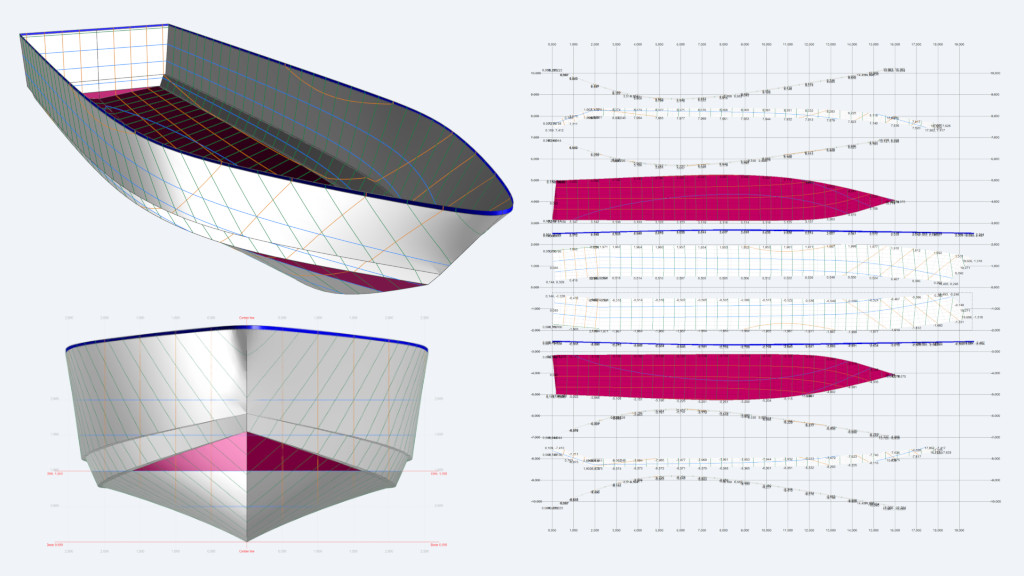
Common mistakes in Maxsurf Modeler projects

Navalapp - Common mistakes Maxsurf

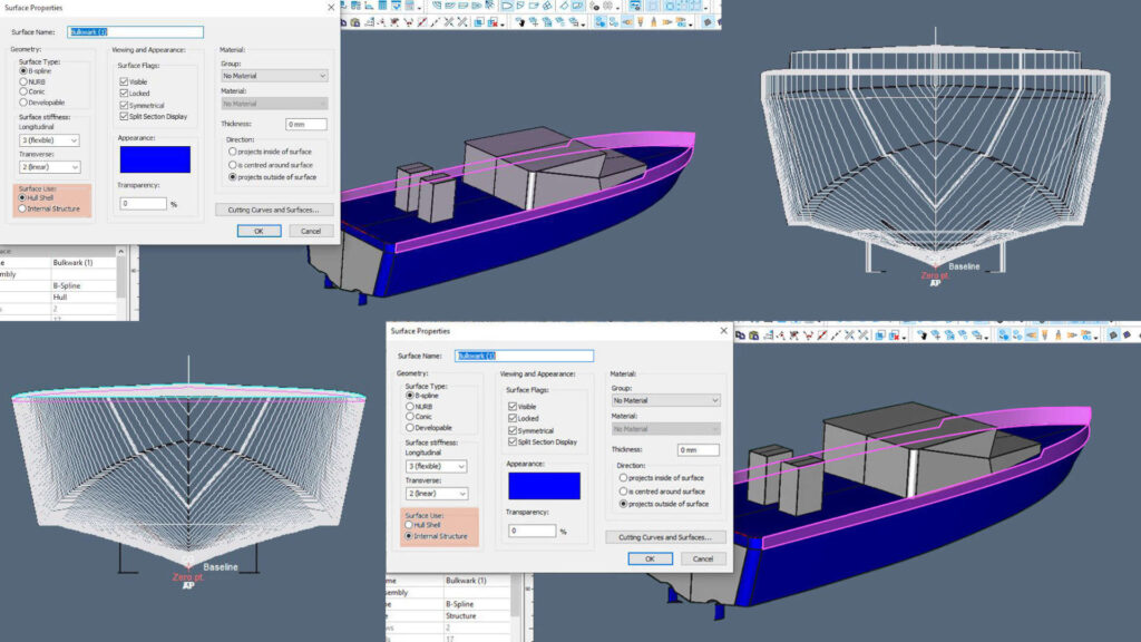
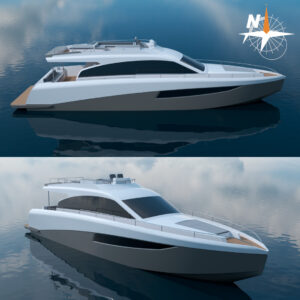
Maxsurf Modeler users often try to create a model that closely resembles the real boat. That is, as if it were a rendering intended to promote the project, including all kinds of details, both internal and external. This idea is common among students and professionals in the area.

However, the first thing to remember is that Maxsurf Modelers’ objective is far away from that: it is a software in which the hull lines are modeled as closely as possible to the intended shapes, but always keeping in mind that what must be modeled is what provides buoyancy reserve for hydrostatic and stability calculations (for use in Maxsurf Stability), the part of the hull that intervenes in the resistance (for use in Maxsurf Resistance), etc. In other words, only the surfaces that will help us optimally carry out the calculations in the other Maxsurf modules need to be drawn. Considering this, users should avoid, for example, modeling non-watertight bulwarks that allow the free circulation of water between the deck and the exterior, non-watertight superstructures, sails, rigging, etc.

In this article, we will outline some common mistakes made when creating models in Maxsurf Modeler. While I have made some of these mistakes during my professional career (making mistakes is a natural part of growing professionally), I have also encountered others during my academic work with students.

1. Common mistakes

1.1. Modeling the main deck below a forecastle or a poop deck

The forecastle and/or the poop deck must be modeled when the volume between the main and forecastle decks or the main and the poop decks meets all the watertightness requirements prescribed by the standard of application (International Convention on Load lines, rules of a Classification Society, national regulatory standards, etc.). This volume must then be considered a buoyancy reserve and must be included in the stability calculations (cross curves, stability curves, limiting KG curves, etc.).

In this situation, it’s important to avoid modeling the extension of the main deck below the forecastle or the poop decks because Maxsurf may interpret it as two decks, leading to erroneous results in other calculation modules. The main deck should only be modeled between the forward bulkhead of the poop and the aft bulkhead of the castle.

Images 1 and 2 feature a tanker with a stern poop and a castle where both decks meet the watertighness requirements. Image 1 depicts this common error. While the image shows the case with a stern poop, the error will be the same in the case of a forecastle at the bow.

Image 1. Main deck (red surface) modeled under a poop deck (the surface corresponding to the poop’s forward bulkhead has been hidden for clarity).

Instead, the main deck must be modeled between the forward bulkhead of the poop and the aft bulkhead of the castle only, as shown in Image 2.

Image 2. Main deck modeled between the forward bulkhead of the poop and the aft bulkhead of the castle only.

1.2. Omission or incorrect definition of the stern and bow perpendiculars

In a rush to finish modeling, practioners often forget to set the perpendiculars in “Data” —-> “Frame of Reference.” This error will generate problems in the calculations carried out by other Maxsurf modules, such as the Stability module.

For this reason, when finalizing a model, it is always recommended to verify its hydrostatic characteristics, given that, for example, a negative or null value of the unit trimming moment (“MTc”) would mean that either the user has forgotten to define the perpendiculars or has defined them in positions not coherent with the model.

Image 3. Model of a tanker where the aft and forward perpendicular have been incorrectly defined.
Image 4. The null value of the unitary trimming moment (“MTc”) in the hydrostatic characteristics indicates there is an error.

1.3. Incorrect bulwarks modeling

Regarding the modeling of the bulwarks, the following are common mistakes:

– Bulwarks with openings that function as drainage of water embarked on deck

These drainage openings are regulatory in some Administrations.

In this case, if the user wishes to model the bulwarks for some reason, they must be defined as internal surfaces and not as hull surfaces since the space between the deck and the top of the bulwark is not a buoyancy reserve (there is “free communication with the sea”).

In the following example (Image 5), we have modeled the bulwarks on a pilot boat:

Image 5. Bulwark modeled correctly as an internal surface (not a hull surface), for aesthetic purposes only, because it has drainage openings without means of watertight closure.

By doing so, the sections shown in Image 6 will be the ones considered in the stability calculations:

Image 6. Sections to be considered in the stability calculations when defining the bulwark as an internal surface.

As Image 6 shows, the volume between the deck and the upper end of the bulwark does not constitute a buoyancy reserve, given that the drainage openings of the deck bulwark communicate freely with the sea.

– Bulwarks without openings (a) or with openings with mechanisms that allow the drainage of water embarked on deck to the outside, but not on the other direction (i.e., they do not allow flow in the direction “sea – deck“) (b)

Image 7. Example of a case where the volume between the deck and the bulwark’s upper edge can be considered a buoyancy reserve.

In this case, the bulwark surfaces could be modeled as hull surfaces, and the volume between the deck and the top of the bulwark would act as a buoyancy reserve, but only up to the angle at which the water would reach the top of the bulwark at some point along the length.

From this angle on, the ship will take on water on the deck and will not be able to drain it outside. In many regulations, it is established that from this angle, the stability curve has to be “truncated,” presenting a discontinuity, and the righting moment has to be considered zero (from this angle on, the ship would reach the “capsizing” angle).

Image 8. Bulwark modeled as a hull surface since it does not have drainage ports. or, it has clapper-type closure mechanisms, which allow the flow of embarked water to the outside, but not the flow from the sea to the deck.

In this case, the calculation sections would look like this (Image 9) in the Stability module. When comparing Images 8 and 9, we can notice that Image 9 features an additional volume.

Image 9. Volume between the main deck and the bulwark, considered in stability calculations as a buoyancy reserve.

1.4. Considering that the number of rows of control points cannot exceed the number of marker points used when loading the grid of each section

This is another common error, given that there may be more rows of control points than the number of markers loaded in each section.

Marker points are utilized to adjust surfaces to them. They represent points on the linesplan that belong to the hull and guide the creation of surfaces.

Control points are related to the surfaces but are not part of the hull. They belong to the surface mesh and can be moved to change the shape of the surface.

1.5. Generating flat surfaces (straight sections) with more than two rows of control points

The stiffness of a surface refers to the degree of the polynomial used to define its curvature. It can be defined in both the transverse and longitudinal directions. Since the higher the stiffness value, the greater the curvature, some authors may refer to “stiffness” as “flexibility.”

When the sections of a surface are straight, it is enough to use two rows of control points combined with a transversal flexibility equal to two. Using more rows of control points is unnecessary and would unjustifiably stiffen the ship’s mesh. Furthermore, if a transverse flexibility greater than two is also assigned, the surface that is actually intended to be flat could slightly undulate between the rows of control points defined.

Image 10. Surface of the flat side of a tanker. In this case, it is enough to have two rows of control points and transverse flexibility equal to two to model it.

2. Conclusion

In order to use a model correctly in the rest of the Maxsurf modules, it is important to understand how the Maxsurf Modeler works. Before creating a model, we must analyze the volumes and surfaces that will be included in the model and how they will impact subsequent calculations based on naval architecture concepts. Incorrect inputs can lead to inaccurate results from the software, which may result in misinterpretations and unnecessary changes and delays in the project.

Maxsurf course

Would you like to become proficient at modeling vessels of all types and lengths using Maxsurf, while also learning various concepts related to Naval Architecture and Yacht design? In the Maxsurf 1 course, the instructor will lead you through the process of modeling two vessels using Maxsurf: a sharp-bilge Pilot Boat and a Sailing Boat with a round bilge.

By the end of the course, you will not only know how to model hulls from a linesplan, but you will also have learned how to model details such as appendages, propeller tunnels, bulwarks, cabins, skegs, forecastle decks, and more, how to use modeling techniques and most of the modeling commands, and how to interpret the results obtained and validate your models.

Maxsurf License

Navalapp PRO members enrolled in one or more courses are entitled to a Maxsurf Ultimate Academic Version License (check “Eligibility”). The software includes the academic version of the modules Modeler, Stability, Motions, Resistance, VPP, Multiframe, and Shape Editor.

Do you want to read more articles like this?

Related

Courses

Go to Courses

Merch

Go to Merch

Send us a Message